
17.4.3.2. Linearization
This is a crucial step that compensates for the non-linearity of the print. The factors that affect the print are the Print mode (resolution, dot size, speed etc) and ink / paper interaction (dot gains). Simply put if we tell the RIP to print a 15% Cyan dot on the paper and then actually measure this we will probably find that the measured dot is more like 50%. This is caused by the ink spreading when hitting the paper. This is what we call non-linearity that we need to compensate for so that we get a predictable and repeatable behaviour.
The process involves printing of single ink channels patches from 0 to 100% (as in Single Ink Limit) post limiting of the channels as was carried out in the previous step. So the same patch file as in the Single Ink Limit section will be printed but this time any ink restrictions that were set would be applied to the patches.
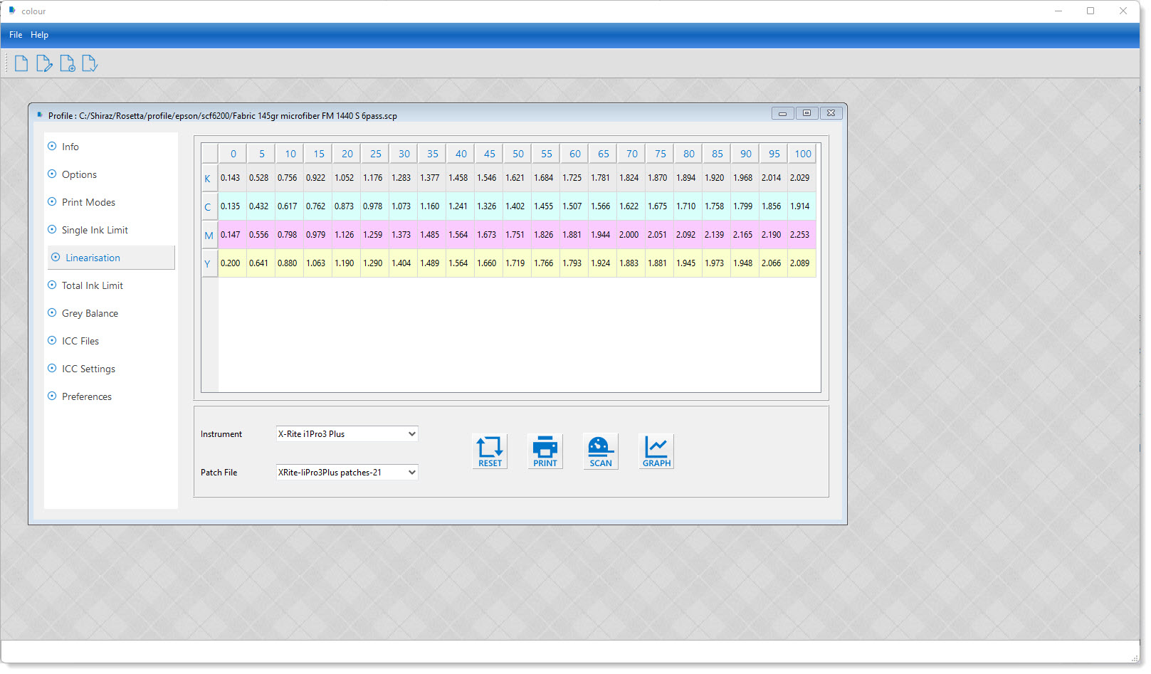
Once the chart has been measured click on the Graph icon to display it graphically. You should now see a similar window to the one shown below.
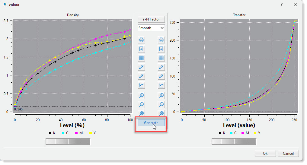
The left hand-side graph shows the measured data for all the channels. This effectively demonstrates the behaviour of your device when printing on the selected media and inks using the currently set print mode. This behaviour would change if any of the factors mentioned changes.
As can be seen the behaviour is non-linear and in order to compensate for this we would need to apply a 'reverse curve' to the measured data in order to achieve a linear (45degree line) graph. this can be done by simply clicking on the Generate button. The system will now calculate the linearization curve and display it on the right-hand side.
The system provides for smoothing filters that will generate smoother curves for the read values. This might be required because of the imperfections in the print and any inaccuracy in
readings. Select Smooth and click on the Generate button and the linearization curve is then regenerated. For even smoother curve generation there is the Very Smooth option that might generate more desirable curves.
We also provide additional correction that compensates for what is commonly known as 'Optical Gain'. The Yule–Nielsen effect (Y-N Factor) , sometimes known as optical dot gain, is a phenomenon caused by absorption and scattering of light by the substrate. Light becomes diffused around dots, darkening the apparent tone. As a result, dots absorb more light than their size would suggest. The default value of 2 is a good setting for most cases but can be changed for each channel individually if required. The valid range is between 1 to 9.9 with 1 having no effect on the curves. Remember to click the Generate button after changing any of the parameters to calculate the new linearization curve.
To visually examine the input / output values of the linearization curve, click on the colour channel required and use the thumb wheel to move the cursor.
Click the OK button to exit with save.