
17.4.3.1. Single Ink Limits
In this section we will determine the maximum ink level or density that needs to be set for each ink channel, this is done mainly to reduce the risk of over inking as well as ink saving and costs.
The values here will affect single ink channels only. On most modern high resolution printers the maximum density possible (or required) is achieved well before the maximum allowable (100%) amount of ink is reached. Any amount of ink over this threshold will only contribute to over-inking and drying problems and even reduction in colour gamut.
The actual procedure for determining the desirable ink limit for the channels is to first print the associated single ink chart provided for your instrument and then measuring it. The measurement can then be graphically inspected and the ink limits set accordingly.
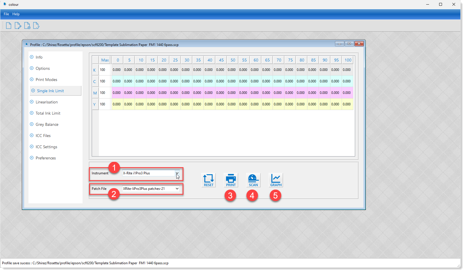
We would first need to select the measuring instrument that we are using from the list of supported devices as shown below.
-
Select your instrument.
-
Select the number of patches required.
-
Print the patches.
-
Scan and measure the printed chart.
-
Inspect the generated graph for the measurement data.
We will now cover these steps in more details.
First step (1) is to select the actual measurement instrument that you are using. You will now need to select the desired patch file (2) available for your chosen instrument.
Once we have selected the instrument and its associated patch file, we need to submit and print it (3) from the printer queue on the Rosetta Server. An example of a patch file is shown below.
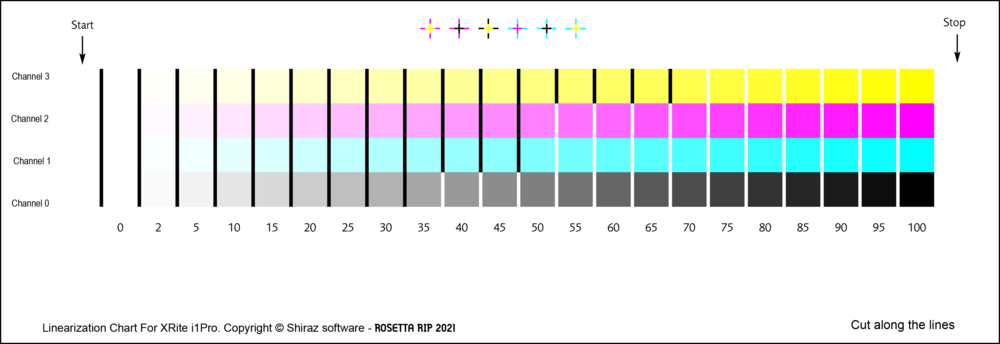
The patch file includes all the ink channels from 0 to 100% in discrete steps. Once the patch file has been properly dried we can move on to the next step which involves the actual measurement of the patches by the instrument. click on the Scan icon (4) to launch the Instrument Panel window where we can connect, configure and then scan and measure the patches.
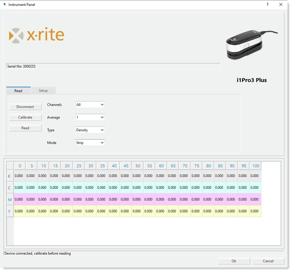
You should first check and configure the instruments settings in the Setup tab.
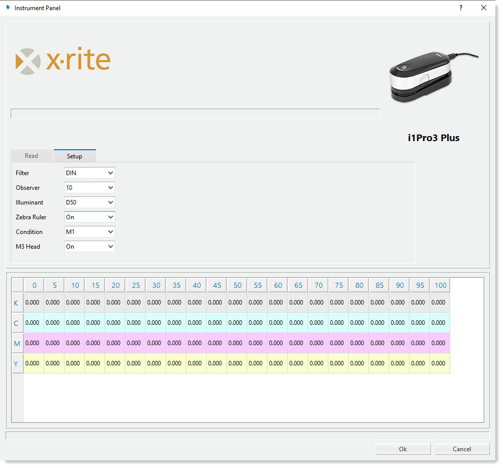
This section shows the list of available parameters that can be configured for your selected device type. Once you have completed the setup, make sure that your instrument is connected to the computer and is not being used by another application. Now click on the Connect button.
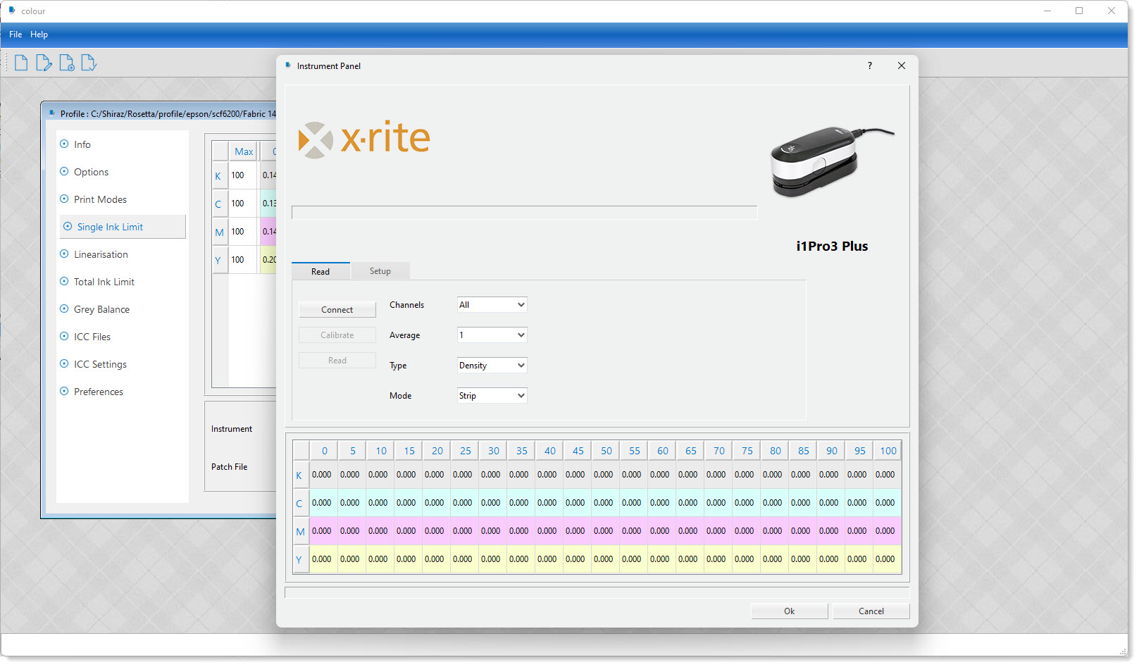
The system will now attempt to connect to the instrument. If successful, a corresponding message will be shown in the status bar of the instrument panel. You should also now be able to see the serial number of the instrument on the top status bar. If the connection was not successful then make sure that the device is connected to your computer and no other application is using it and try again.
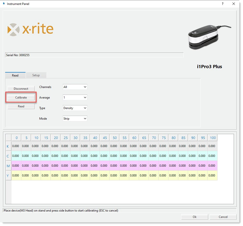
After successful connection you would first need to calibrate the device by clicking on the Calibrate button. Now follow the instructions shown in the status bar for your instrument to execute the calibration procedure.
Once the instrument has been calibrated you are then ready to start measuring the patch file. Click on the Read button to start the measuring procedure.
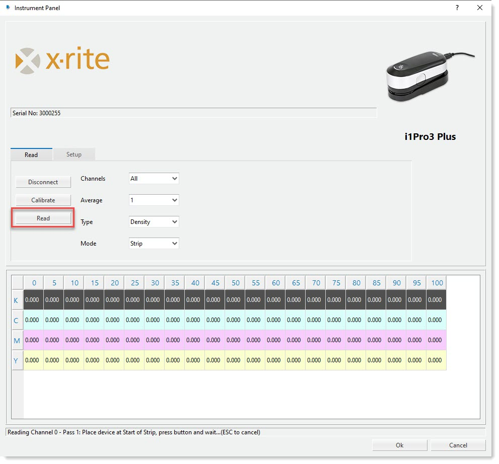
The ink channel that should be scanned and read is now highlighted with the corresponding instructions shown in the status bar. The system will now loop through all the ink channels and show the values read for each one that has been successfully read. Click on the OK button to save and exit the Instrument Panel window after finished reading all the channels.
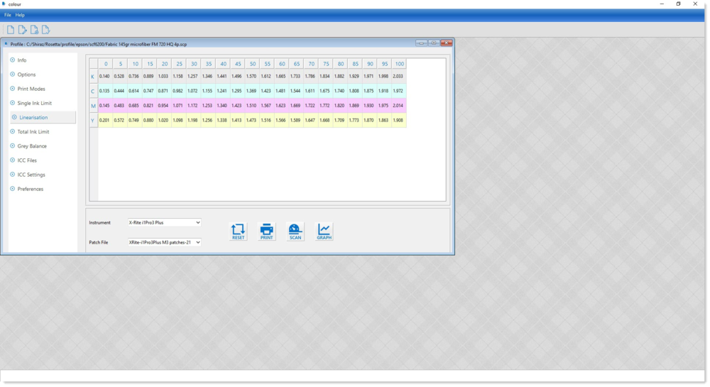
The values that have been read will be shown in the table. Now click on the Graph button to display these values graphically and use it to set the ink channels limits.